- 您现在的位置:买卖IC网 > Sheet目录338 > LV5216CS-TE-L-E (ON Semiconductor)IC LED DRIVER 10CH CELL 36WLP
LV5216CS
2) I 2 C bus transfer method
Start and stop conditions
During data transfer operation using the I 2 C bus, SDA must basically be kept in constant state while SCL is “H” as
shown below.
SCL
SDA
ts2
th2
When data is not being transferred, both SCL and SDA are set in the “H” state.
When SCL=SDA is “H,” the start condition is established when SDA is changed from “H” to “L,” and access is started.
When SCL is “H,” the stop condition is established when SDA is changed from “L” to “H,” and access is ended.
SCL
SDA
START condition
th1
STOP condition
ts3
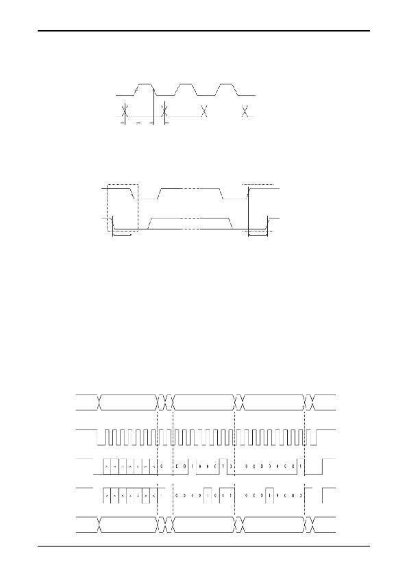
Data transfer and acknowledgement response
After the start condition has been established, the data is transferred one byte (8 bits) at a time.
Any number of bytes of data can be transferred continuously.
Each time the 8-bit data is transferred, the ACK signal is sent from the receive side to the send side. The ACK signal is
issued when SDA on the send side is released and SDA on the receive side is set to “L” immediately after fall of the
clock pulse at the SCL eighth bit of data transfer to “L.”
When the next 1-byte transfer is left in the receive state after sending the ACK signal from the receive side, the receive
side releases SDA at the fall of the SCL ninth clock.
In the I 2 C bus, there is no CE signal. In its place, a 7-bit slave address is assigned to each device, and the first byte of
transfer is assigned to the command (R/W) representing the 7-bit address and subsequent transfer direction. Note that
only write is valid in this IC. The 7-bit address is transferred sequentially starting with MSB, and the eighth bit is set to
“L” which indicates a write.
In the LV5216CS the slave address is specified as "1110100"
Start
M
S
B
Slave address
L
S
B
W
A
C
K
M
S
B
Resister address
L
S
B
A
C
K
M
S
B
Data
L
S
B
A
C
K
Stop
SCL
SDA
(WRITE)
SDA
(READ)
Start
M
S
B
Slave address
L
S
B
W
A
C
K
M
S
B
Data1
L
S
B
A
C
K
M
S
B
Data2
L
S
B
A
C
K
Stop
No.A1968-6/8
发布紧急采购,3分钟左右您将得到回复。
相关PDF资料
LV5217GP-TE-L-E
IC LED DVR 3CH CELL PHONE VCT16
LV8498CT-TE-L-H
IC MOTOR DRIVER S111 WLP
LXC100-4200SW
POWER SUPPLY LED 100W 4200MA
LXC120-4900SW
POWER SUPPLY LED 120W 4900MA
LXC150-5950SW
POWER SUPPLY LED 150W 5950MA
LXC25-2080SW
POWER SUPPLY LED 25W 2080MA
LXC35-2900SW
POWER SUPPLY LED 35W 2900MA
LXC40-3330SW
POWER SUPPLY LED 40W 3330MA
相关代理商/技术参数
LV5217GP
制造商:SANYO 制造商全称:Sanyo Semicon Device 功能描述:Bi-CMOS IC For Cell Phones 3ch LED Driver
LV5217GP_10
制造商:SANYO 制造商全称:Sanyo Semicon Device 功能描述:3ch LED Driver
LV5217GP-E
功能描述:LED照明驱动器 RoHS:否 制造商:STMicroelectronics 输入电压:11.5 V to 23 V 工作频率: 最大电源电流:1.7 mA 输出电流: 最大工作温度: 安装风格:SMD/SMT 封装 / 箱体:SO-16N
LV5217GP-TE-L-E
功能描述:LED照明驱动器 3-CH LED DRIVER RoHS:否 制造商:STMicroelectronics 输入电压:11.5 V to 23 V 工作频率: 最大电源电流:1.7 mA 输出电流: 最大工作温度: 安装风格:SMD/SMT 封装 / 箱体:SO-16N
LV5219LG
制造商:SANYO 制造商全称:Sanyo Semicon Device 功能描述:For cell phone LED driver
LV5219LGL-MPB-H
制造商:ON Semiconductor 功能描述:MULTI-FUNCTION LED DRIVER
LV5219LGL-TLM-H
制造商:ON Semiconductor 功能描述:REEL / MULTI-FUNCTION LED DRIVER
LV5219LG-MPB-E
制造商:ON Semiconductor 功能描述:MULTI-FUNCTION LED DRIVER - Trays 制造商:ON Semiconductor 功能描述:LED Lighting Drivers MULTI-FUNCTION LED DVR 制造商:ON Semiconductor 功能描述:JTRAY / MULTI-FUNCTION LED DRIVER
